Project Red cpu build

steve g

New Member
Jul 29, 2019
445
0
0
some of you might know me...i've been out of the ftb/modded mc scene for a while due to Real Life(tm)

but I'm back in it..with a nice machine to play all these new packs with. While im messing around with SkyFactory...i found a redstone pack which is absolutely *perfect* for building all sorts of cool redstone/pr stuff.

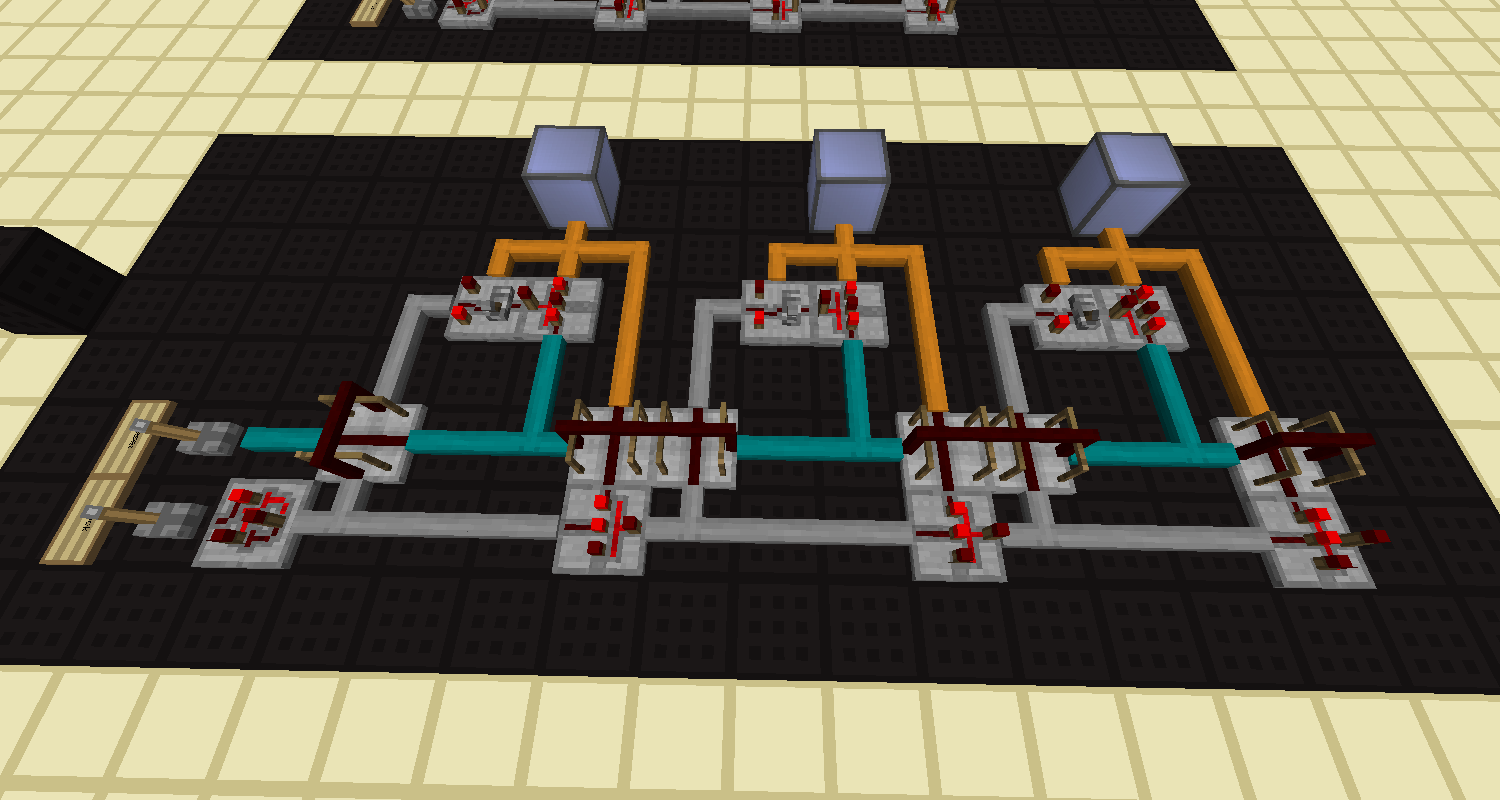
I started on the idea of a very simple cpu, something that could implement BrainF*ck (google it...not hard to find info on it ;) one component this cpu needs is a binary counter. playing around with PR's toggle latches, I came up with this
KSGmXI2br9XwJrQQxFtsyxIlq2TzqZ5mg-h1654GAQPHTpWvpk82zYuYg55RTGOPvVIYuuD3sbkYmr08MwtxwLRJThn_2e85cPDn86LwXb6K_a05ALASfY5wHBt54X0Oipng8HxPGlXescfoz9OVqGBXgidCt_O010FhTwP360YtTcFepKOrTghQ6Z807Q8OAjOfXFnPadrTDwjaBOehLZ8gRv7lHrFfa6Patii8IM-SLDtPwNQA0UKjFLONdyb9DXG1pWfT-SWN6ZcqVoz7aqXGSBkz-pQNzD4oQptajoztLAZP_UyeDiWZV49qgtXMygBQNTn2mpR8gKpsNJF7xFPAl6oyQ3CJt37kdkg0oC_ocU4U5uMw9YONLJuhO7XnLfAz5b7ON3nNUZtBPA3ztDDpau_EyGS5OctKuwdrQhnHaH9updOseMnnUPGuufzTmvJUzqPv9ivcv_2H1Jha1nK-u6MDXpHQfe6E9twt6WGDDjLGTZEiff8WRAJFBHMxqEKNkj8uQOhZabm1gEgwDsYX2j8vHH_ghHoJk8X6IGIwXhjtsY1fps01TcjdkZh1_dGXdqMk16B9haAYnU2bMlIfjmc4Od_JN06p2N9vvBKUJVfYtEd30duyQLk0TGkHI91-Oz3iO0zakR_RqUC_J2R3cbShfyycq38=w1500-h800-no
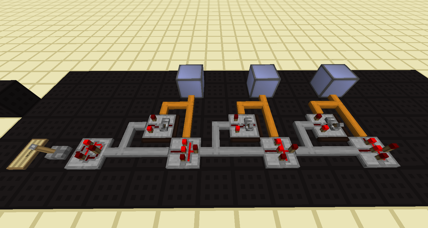
just a basic +1 counter. it works very similar to a piston based counter...but without the cool 'instacarry' traits you could get with normal redstone

That's neat...but it needs a reset function:
J3ARhMhLekfSgSKeb1WzRjrDirFQeAUpru7MPGMaDFFB9feIvgCZTRxAV_pnQAXSYVq8WHQn81nHZj_M8WkK6rmWevjoYCZcE74EoUWstkwyQlO-vcSo6HrP8OacG7wtHQs4tAfNLUoQhs5gxZc2GU7K1iDU2d3FGrI84FUcMmDhOjDe5CVvR-JVFmGkvG6qzzkr23G2FoGCFwCI4K97yl1D4XdaPGbv39f2upT26tPVSWVL6Ej4SaYuhHt0PfWGtttHEdH1_DFk5y8Wzgoc1qKouD4igw7cpKJh-tMZ5eQJqlwmruPIUpoDehFNFOP3yPCEI4BxtLLLl0LO0OQe0dJz-zDzy6m8kwcYZ1KtVK06pH9fl1rmDXoYdEfHtYBVLGXiqI6teAh3Ob6lv-MNqw5b_s1erh-XQ7xZtSOr1IIkmw5MCczL5XVwTLC66o9hunriFDdCt7NTD1CQX8nyJT3Nu-FXHxzINCdGXz-MmBtyNDFJZJfGsiuvhZjmLnpKKBfYW3ZN7Txp24XqlzL1asbInYHiAo1yx4PkMCP1mo4RdnvzZ7rHdJsraeufr5t7PJWEYBZeHeS4dv4ePepSApSrjr3dQXUqyDLEGrijtpRGiJm7tVFqv-PhtJWMkiVUtd3XLlB8RGvA-tMvA29rWRQoRjq_uVlJtCU=w1500-h800-no
simply adding AND gates to the toggles between their outputs and the reset line will reset the toggles. The logic there is to only toggle the latch if it's on

But that's not enough...we need to be able to load in a value (aka load branch)
hHTgHBzPpiV65KkzfVxhCRlB18u7QkMEIQ-RXE7NS57LyFekUG4cqbenBrvOGWiwlVxkgowpBS-Sf56TKqQTNbwGb1-wBU8ru2MNgJHHCpiNFQCT9jib_BWoN3LGYw6D_bgs221nN4KSG864BoWp5uR-lf3cyZqpoumQfL77YNV5S34bqfqEq7fguw83zv86NHCbnNpSU-Gu5A2jpMveRDuMUfQ7t4-GubJmU3SPeFKeMfgcGl5PSvETVAP64J0erEJnBcpr2mIqEhEmMZg6tuOP5e8gYt4dFgoj9HgNiiTBAw9KZKTqQ3-fWOpCnOd8Otb5XjYwRr_RxZzGDs4KXV1jVAzPYhBohuj8CxS_hfGuSDHbhuG6svYeQ7gl_BcO9SrHBhPDADwAwqj2xHwW6fJKvVQJ_U1kiYqTw3rMgqea7QnWmk15N683uPfv14ezl5Z-MSSbkquJnwBvJQtoY1Ev_i1Ml7YEZHWqEsWUcEN_qBz3zpIZ_xzz994C7LyzF23tj0z_yFougDN82JY4C9ozFzMrU7Dpstr4TwkkOCams37YZZmtX3at-Vr-YJppHFC3Vs81o9pRLwD05p5StEhh7Ot1bAQbaJ5cKMHnQan8priERoXVwbnMN9JdxC-dtyrRYy9uT3MYhDkCIWjUHmrbssb2qbmv5SA=w1500-h800-no
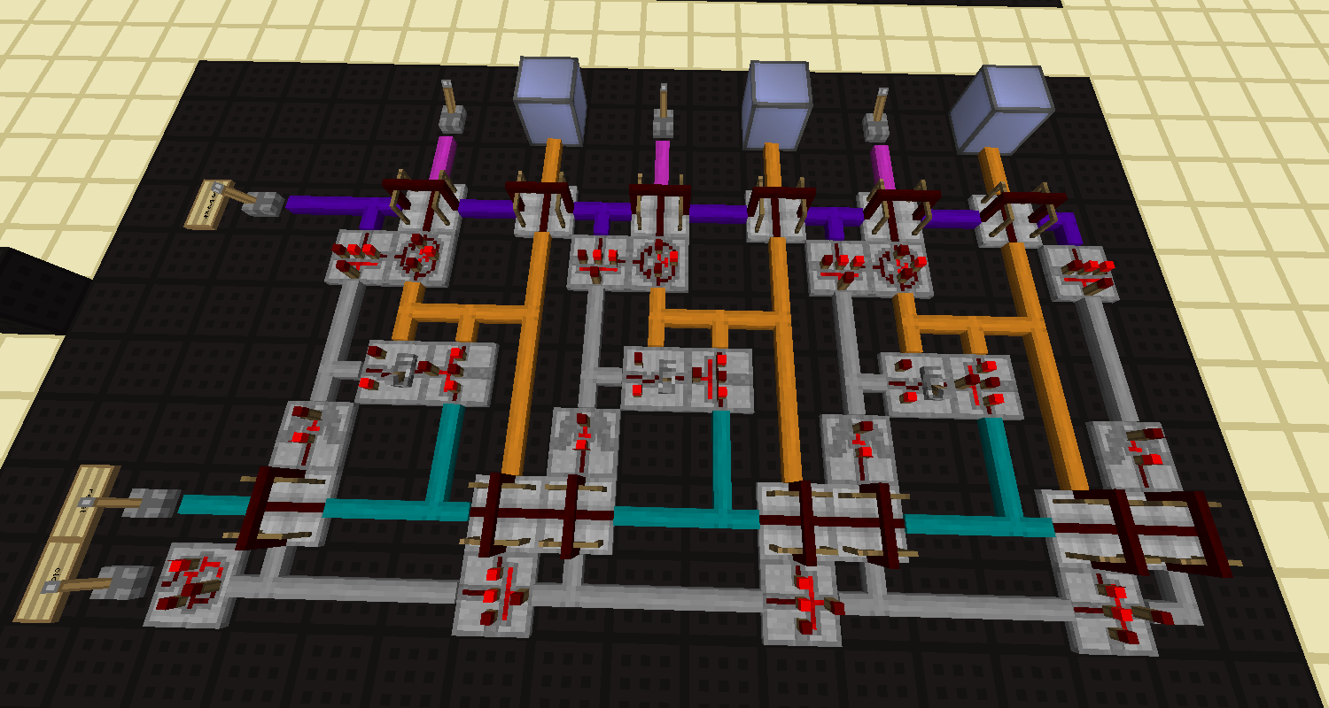
I'm using xor's on the toggle output and branch inputs...the xor determines if the toggle needs to be
switched if the toggle output and the branch input are not equal. Had to add buffers to keep the signals from the xor's triggering the clock line

We're almost there. The circuit can count up...but not down. lets add that as well:
TXsY3xLM-o0tRzxeX02Ud_9tltAe28K83LeZQ0Kv_igNx0ArCzJXDe9wLMIbgEisMNcRMh0A8BztsDph_5okAndFnplC0JOcGAA9aFfNmc9Juvk2DrDlgN2_pzL1IRJ1QdThJf8QxgJYYOieqhv5qR12L9euQCr8kwvNarL_X2O0bVnx25RvPUk4ff0WMxn0RCZ0oQ3PoNjo4_4TjDNuay2Rcff58At36QVTjmvG0kQ-y8HSfecge6pDPXCA2YxArPq6qHOvV-v1UNdCZafE-hYOfSFGWE0LG84ENwsHW9s0CddD2DswQ7pNQeAvePS_xNKbYcx-iNZVnJbJhC9G6jS_7Bb_qpbjeBtXUpzRNIdSIsHgKaPRPAn18HSBU2NNJQAoGJSZka0PRntTeTTkoX5YWogO6fjlIv1ZxazoH-wNqM9qPeuXpck-pK4HoQsdHMmhxclOuDcU5bd2-d4XdHNtO6iLNjV0k_E51kNT4e0MsRenEtqvwGtj6-bBH359GfABNgyFTyq4kQQm3v_PLwhycOZ2FYmaV-pvbFPmb16_NBWsbmitayHmoKwcOWgXuUz0pkv5J98vp10PzOX_MpPgBFHxo7cp80oC8om8gwu0sEfzPYcM4hySxY3nukF69j-ydq5GF11x_GwzhdOFDJlj5ciVAdEXnbI=w1500-h800-no
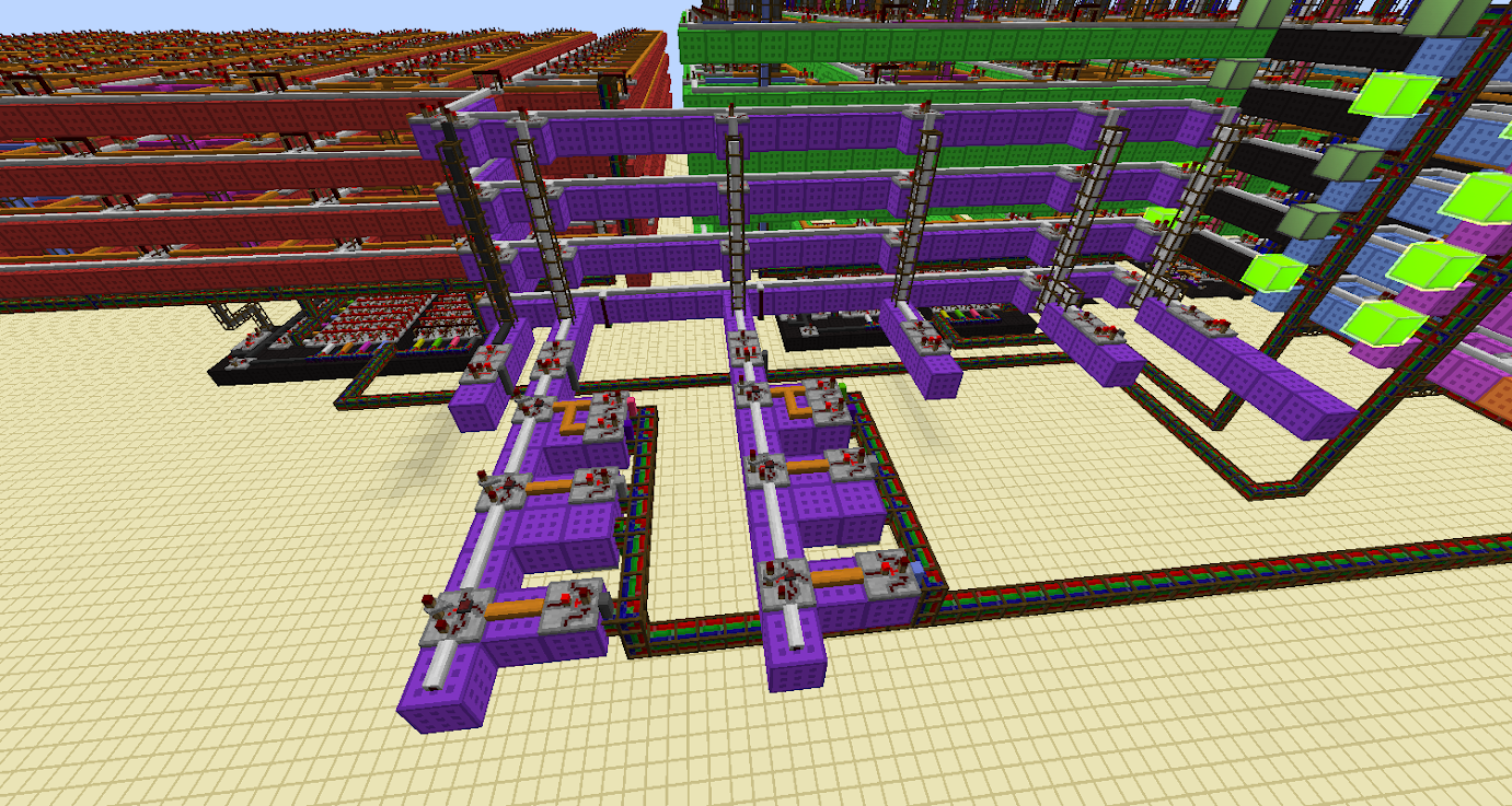
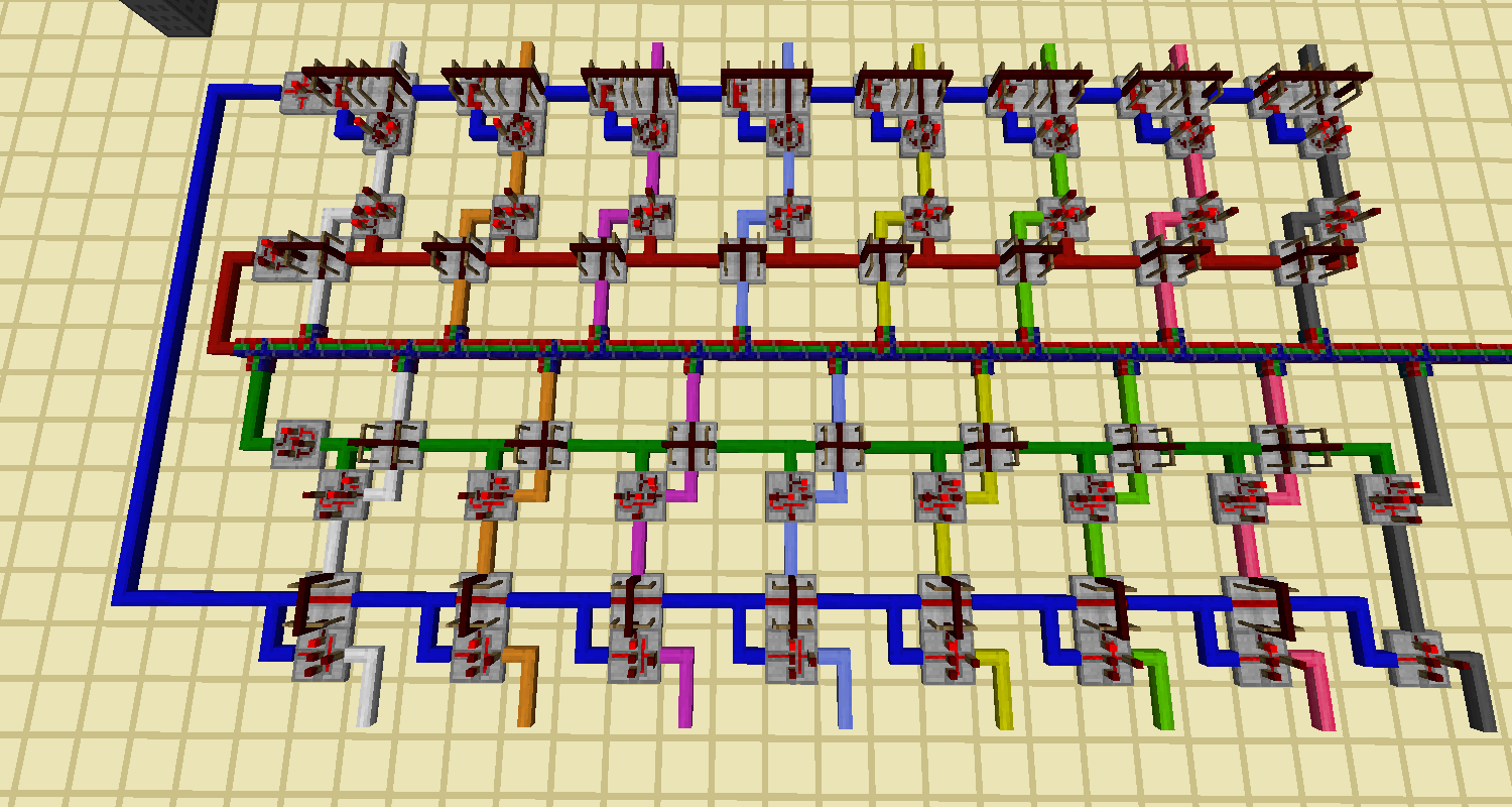
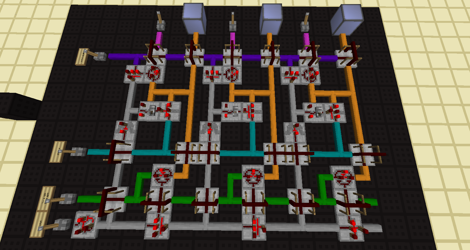
here the green wire controls an xor gate on each toggles output. if the green wire is off, the signal from the toggle goes through unchanged. if on, the xor inverts the outputs...causing the circuit to count backwards!

I came up with this pretty much by trial and error. I tried implementing a counter using a ripple carry adder and wasn't too happy on its size and complexity (needed latches, output fed back to inputs, busing inputs/outputs all over the place, timing issues...yaaaa). This circuit is not easy to look at either but it does exactly what a bidirectional binary counter needs to do, with all the functions you'd expect

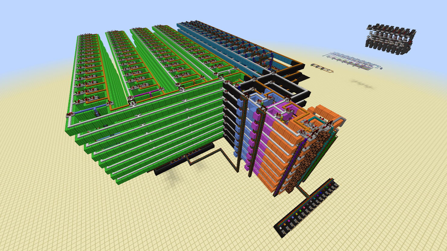
As you can see it's easily tile-able, the image only shows 3 bits implemented. I have an 8 bit version of this for the cpu build im attempting:
issLK7YY18CA1Qc_JK4udjMFkPPFW1vLEOXPtV6Il2Fqd4iHm4P-CZ5p5OR2cWxcjum2a0MkIrALzrPxak21bQmrQzmjVpmWRVZz7djwBNBGLVHUMgP3WFRsFEqzu_VLqS_PtTEin-GqPwaHn4WpTWhybAy-xQi0i11fODNWVM37v1cAnG6Iyw9Rz2nCWh9RJpjyy44u26EvNYsq-MdJsbqGaLe4mq6e1UJOeM1YUE03k0-j5hZxa_S9IwA5K9I0zY12OxKBNukW5u2YSAO05Hv6F1vaPhYN9OXRCOEs6kKABgHOELNbRCt8eWVT6Moe347dq2ZqqeVfvJDMPVX6W6kwQVn61Eyxr-C3ugZNGGwGGOtKsQCcF_noZBBDlV0urmt2KHkvkryK1fmXNFY743eY0-knRrXOXhY8mqu1rFOy-5m1pAwVPgcy2OnCNVGvlqPNV8fEUv0KldJ_WMfSwmd2JV8X0d9lA7HlUYNoDNU3qFAnY5NypG6zPUaTGIU00ZflTXRVHPnDqv4xcn1GXPFIQ7XceN3jwhWj0tSOoPCuNoS6yj_yHPJeFgKkMDonDsy8KKWijioQ28PYakmfddIQ3VKaf3f9afbgT_xPs3kHDGZ4By1DKa8akf1HekYtUlgP5gnh0nV65kr_pvpbFiyJCdjFYns-cyA=w1500-h800-no
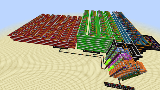
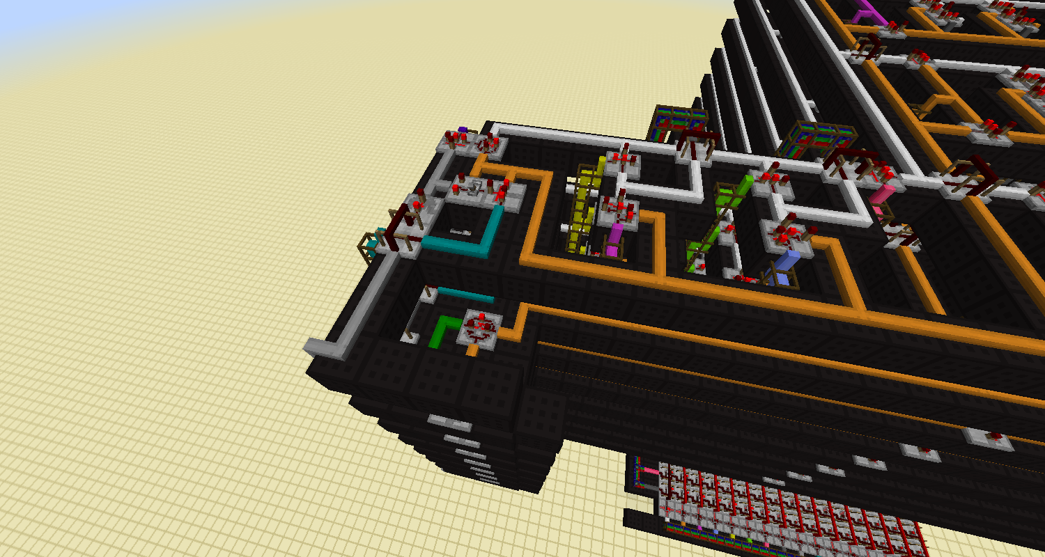
This is being built bitslice style...each layer is one bit of the cpu, and 8 layers making this an 8bit cpu (makes busing *much* easier). On the left side is the topmost slice of the binary counter. just after that are 2 registers and the edge of the ram array (64 bits per slice, x8 for 64 bytes of ram) and far down on the bottom you can see part of the ram address decoder.

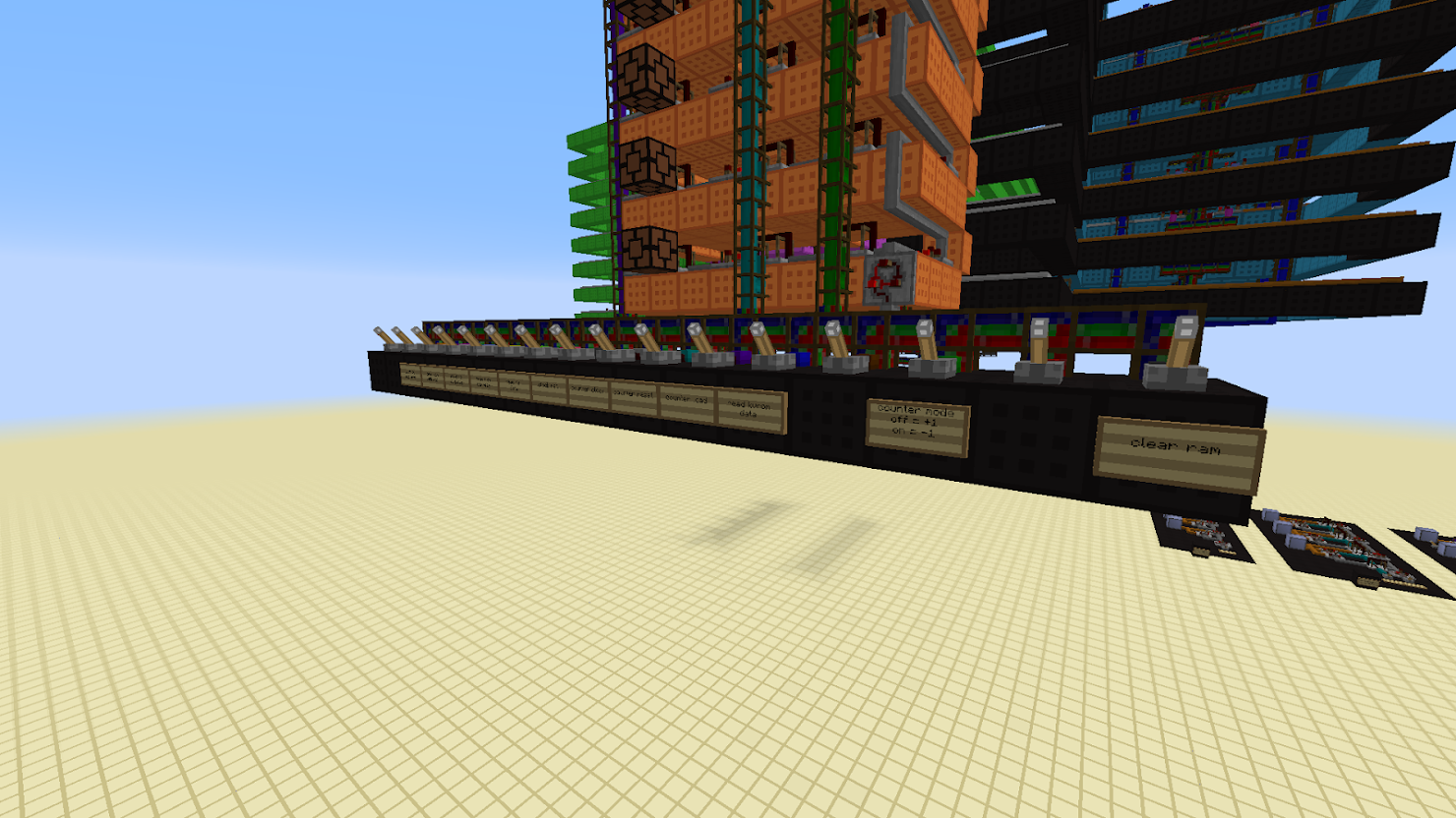
still needs quite a bit:
rom space for bf programs
cpu controller
and something to track jump points in the bf code

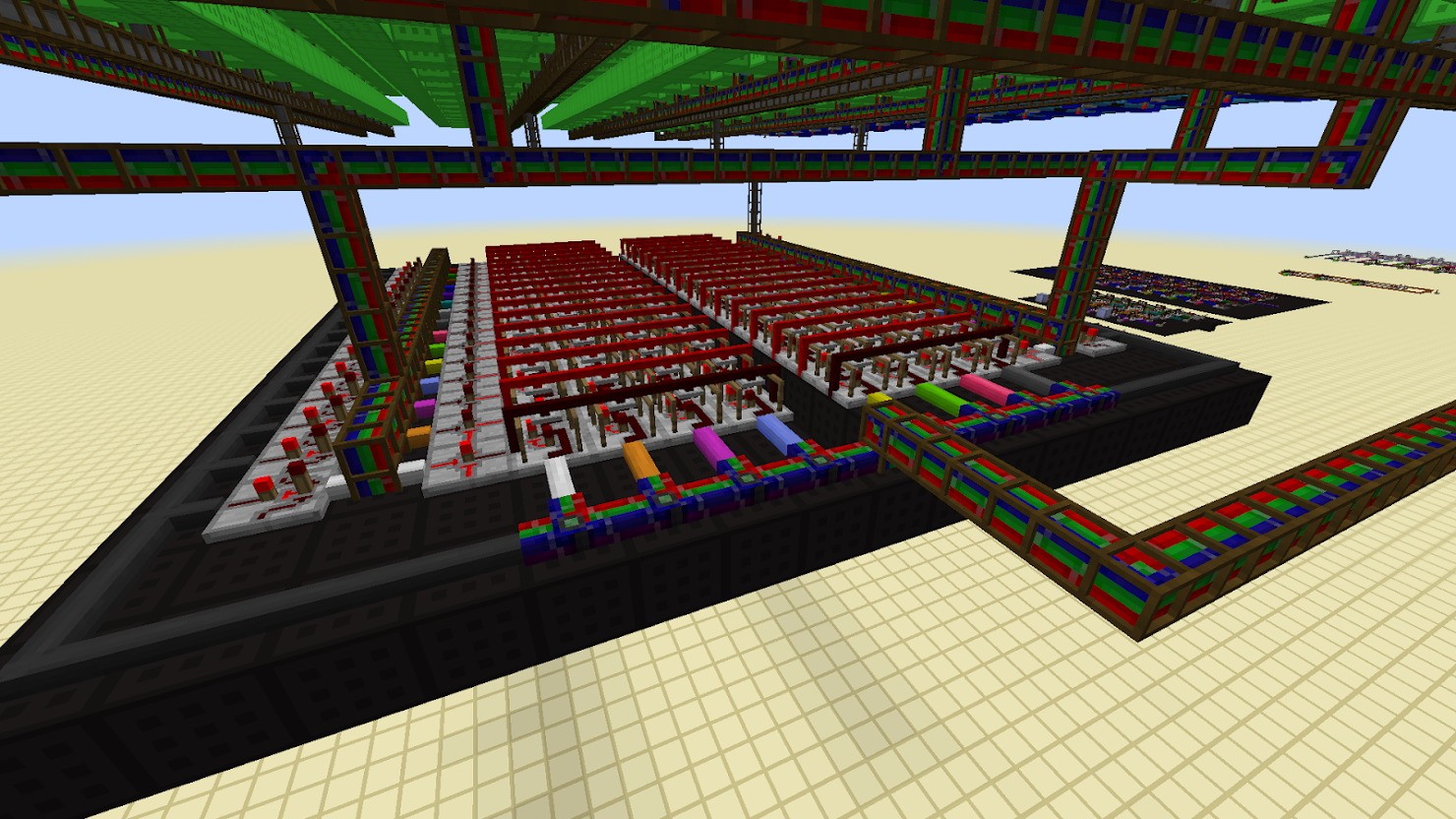
If you look at how a bf program is written, the '[' and ']' commands are the loops. a very simple interpreter would simply scan forward or back for the start/end of the loop if needed...more advanced interpreters maintain arrays on where loops start/end or break out the loops into their own sub blocks of code. I like the jump table idea...and i think i have something for that:
UWKe4n3Wnk9-Gwy6_TCadzw0a0HhiSDpXEQhfEy82WuebSLwy-qn0t93j5NGsaq8Ltw2CiYjvx16ag10F5B0h0A5ojU9VKapkOYpnPJLee--P4CXQBsn1zSGjTtEPaC4X8kCMKE5y90DQx4e1UnNGLprVCjyF1keN_cEQQws938uj4TIlBx674F4JxovbKHrEmSz_MuXnZIhWmq6y0KwDUVGBiJZDdR_aTF0x1PJxCpeEeHV4IuE0CdH521nxIdZ0j-9cgwpAM1Iuu0E-F9hZOE8H_wzVFoYId8otGcZpFM5rhqtrlzQN20p-CH9W1pUlCLMq0XPpg0lQseVtJON6lGZ2xcdeRD8jqRn9KJcAhdCa8-rPfp4cl0lp53glRy9EtG17OQeReTrmmmtyCsreJRbaaeQ9fImkGwubrum5HNUqvhy4Yyja9Ohcz4c38V4FPYKOudpurEEaCBchu1xzW5WVrL6WQ2UKyS0pEcWng7CLo4Eym1MugPJnWl1npqXbe9uh5lSWhdmab6WyuTtlDjFc6uC3pzdmDa2fpvgSvGVUH2LHp78oEZlO5LbWD7EBkcqQ7d9_YRcFjhadPe6RzqdKfH1hpwDojF3FzkIB-E8BqnMnQdve_uFECmEn3X8dhtY05Nt2yoD9q6RwpF575gEW9udeP1b6Sc=w1500-h800-no
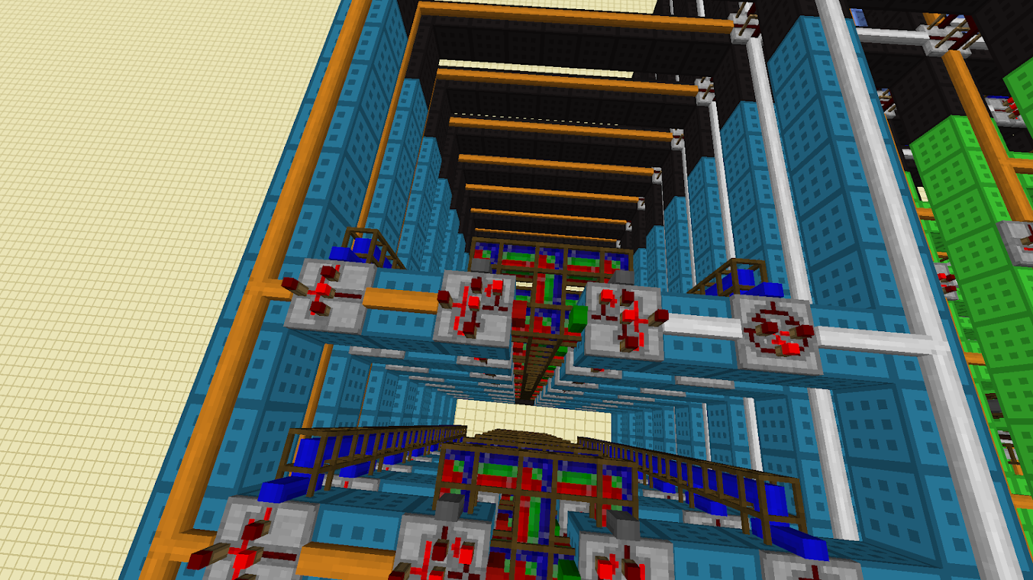
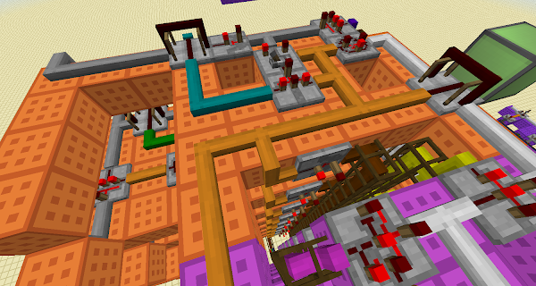
this is what i call KVROM (unless someone knows of a device that does this): key/value rom. The idea is an input value comes in on the input bus. There are xnors on top paired to latches and the inputs. if the input value matches whats latched on the input side then the blue wire becomes active and enables the outputs for the second set of latches on the bottom. If you're familiar with javascript..this is almost like assigning properties with values to an object. You would program one of these with 2 values: a key, and its associated value. This requires 'precompiling' the code as you cant access this memory like normal ram. but it would be highly convenient so that, for example, if i'm at rom location 12 and the instruction is a '[' opcode...the value 12 would be on the input bus for several of these roms...if one responds to the value '12' then the output will show the address of the other end of the loop. Id have to use computercraft anyway to load the scripts into the computer...so programming the kvrom can be part of the loading process. more coming as i work on it ;)
 

steve g

New Member
Jul 29, 2019
445
0
0
I made a bit of progress

dP9rfNy4UaN1DZMCUNZlDkHCbmVUvdHbcfom0PkiCWgOCBC0FYIPgVQAxWlbRpuG98zxyqavxQ_4sqwja-_S5khgPNVMxC0GRW6SRI8yJ1lurL6BSZYNHwJ7ePH-ELO7FJsrs-KUXO9eVWtmqa5GiX9xkofdMhaye3sA7ecM6j0VQbh9NZ7EdgFZLXoxvf9yHipDvplQYVSn5oerSeTVDRbMc2ESnB1Lt7Fr5HHdb5r6gARDFFiYUeqeb6Z6itonaNcNprlKFXsBgt1PstO0u8CIKR_0eyfNSM_2awuIxM5xygVYxCSmzjH4HbSBG8_7ZaUvbmxe4PI_JKhk0L8UIVDArMI2kalY7kZ6snuGhglI_FPNfE1vgj-a2GG20_eMNGpOfNRFwkWcMmqXJph0n1PFqW4qqoqBp_nhUURfgteDMolggX3pMBERZPG2Weo1H7YH1VGoVb5DzGUb85ewOvpUHrZmGLFyA_YkCZkEqzLnHQzkB3IsWiij9KTFOD4WQNZLH4624XHgqkyuG9KH9-Yd5ksmsImH4qw_QGLBJLHNjPuwO6nXgrAFu2tomobRyRFhUb05PBg5ZZBuLACWBTW-IdRZvae0T2Pcfmlivwd8T_WyPPv2xlFJ9BMC3dpoCePRKkDGV6rqir2IbO_uXWC6lQ4TMOpyVtQ=w1480-h832-no
i color coded stuff to make it easier to see whats what. (thats why this redstone pack is wicked cool...worldedit ftw! should give it a try, its in the twitch launcher)

orange is the counter
magenta is pc address register
light blue is mem address register
lime is ram. 4 banks, 16 bytes each
cyan is kvrom. 1 bank of 16 key/value pairs
black is busing and random bits

WnoFWbyI0gAxIHDnyivjRL8lW5CZEHIE-9VxrXJFGy6LrY8G-ILJnvpDetuigqWAAWX9d1Uz1vqpGYgcU_Uc-S6Ve2h9ROQAyzX_5QnvTksryO_monHcnDHwntw_HwY4fbRgs-jTCM9za1TfvnAVwjDTLztS9IBBDHKwzo5mKg9I6h6McL_-jPXqwy0cKoht0plgfWDUlraAyRfSz1x2WYPsvH7qI90QPq3p-FFHcrWqfcPrIDqt6KQWVpw9LZb419XWDqmEhI3ZHNrGFNiVJJ1Yxb20wmG0pwcvEmXb8719qae6Pvd8uCVUI1GnDpAvSMB24lClSwPPzySwpwOSNTqOnNk2l0TurDuPRzxpBgl71ZeXMcV_biJI7fGfx28vj6mtPhpCK_P5mIRAanWnSZmODohZTekFyjctzZ4HF6lGTkJLgybEPYoa63FnRfUu8hupoq8fnrcwluf1mI1paM6xtnAxQBNeTY4rKiS9sWzAPzFBsb-L09n-ox-Cl2RbM_8PohMdoqQMOdFXGq-FmMULcMX0UnLfmUFdTYDGUGoJcX7L4FO5JoZV7lyHMSl_MuUhc0Wp2CnBSM7H5JIklSDNEyfgdxpNzOhXOUXz8nCsLWURXWl43f-yzho1etoyXQHkQIPxYouX9ttrvYMZUXezzJXhuEIciNk=w1480-h832-no
testing area...theres a bit going on in this build, need to make sure everything behaves. added some lamps on the counter to see what value is currently in it.

crXSh27--Jdwi-VZiMhhFwtIWxj2RSoYuRH_L4Iog4XmJr8YB8Kfij84AD7KXitssZAhOl953iIsD9FAuJw_cc8-zH_pXTtOO6VGJyC8xJ4FBENTVaaQqwrL0joP9NbszEoQQsopU58t9GqY2sGWd2olM5e7mWaS4JimB5QRvdif2sYnNh4ysJWQs7Xb1bqhjSKxleETPJ_k5nCOE_-96lw9dixVCCTQAi6PX9gUH18LlnonIArcJoQlCiT_lb_9HtGGOZ-_sRvGn6AHNUT8xSiczABC4lsdOXYWGEVi3WTYDyisMCTaLu6dVZnFJksy3AQzKUH4fjRNy9Vjrt3eQrk1FUeaJVi2kpMTY1BJcHRA77sjhI7sNyaEwmrpZAAV7osNbimFAW_nKAIHo_hGXUW4fi-qZ4E94LRmg4ZwTGVIkafySK_APSUHUnkVnX9N4xOSBg1SjJndPC8d8s44KtMqX54ZLBCX-X2r2zAx_VW1Gsoq7NvytUgPjgWmmV0zfSxKyShDQIMqBBnBODOfYYtau2g-eh3Iy7JFpkd6HNqb8Sz-qAJnDFptkjpiPw6JYBOKg-HeqmYiLaqI0331tkwMwfC2HJVr46P9ch1CGM23hPMJSyuxZcTxetfVynZpuMsGgTxKxio3oZI1JYtODHsijVthxoOiLvg=w1480-h832-no
close up of one of the kvrom cells. this was optimized a bit from the first version i showed you. xors do the comparison now (was using xnor+invert cell in the original...derp) . what you cant see is the blue lines connect to a not gate underneath the stack before it comes back up again on the output side. the bundles in the center is the programming interface. i have a cc script that can load a bf file, convert it into opcodes and figure out the jump addresses. the cc computer will talk to this bus..the cpu itself never touches this line.

3Pf8bbijMs5LifTlmnBIyvhzqedZ9z_KUQwnr5S5Cu45XHQjVz8dz8PG4BRFumm_JSadchbifhujBqQSYd72U8Nti8rC5nYkTURLyXruHr3d00li89aqEpwZp4kNwlT5Ag5Ud4FjUz2Dct5kjS8SV567zYeCL5IL4APEJeUIJXmjUQNAz1lORqZhth0crkocaYOaICzn8XpYdRZBWHg6ZP3UCGZ44W8XqF0gfPGYY7Yo2S0jRiaGRgz5lJ5NEHstCXOLQy9SkrOvwVAIm8f9DO8EIiB9NPcHYU_E-kEIZV0mbEcq0WU2LTgDnY_ac548JSxDuaic6qcmHeVDqP-fIqac6MFk4JetYWIC07oXCBYScI6ZMx-DwhibIeqba3m5NHOFwJIdx_jRJGW61xQTiq-HTHtu7ywPkGDgWcB-8g2doEsxvg1gzxCLZ7SUVO4SR5c_5cT_eAULkJTV-Ymb9afEkQ6woJYuGZjS6ORNbF730m0oFjA_yFVD2IKJaRf-khvjPlHtL_w6DB8AVG9I7GhjwsDrS5ajotKOw3nMbweK5oO2Eem6av-NcCwitAIuheW1ggMYdy5pQ5ys8wka69Nr7HBDKy3nMO1qM7E-E6wdSLh0NZH18wuG56_axQM68dhXOiR9csKh_JWOHIxs0v3Xo33o2gILCEo=w1480-h832-no
the ram address decoder. its 2x 4-16 decoders. the left most handles the lower 4 bits of the address and control which of the 16 bytes in each bank is active. the right most handles the upper 4 bits, and controls which bank is active. the black wire going around the whole thing is the clear ram signal..it just turns on all the banks/bytes and sends a clock pulse to clear the whole lot.

program rom is up next, stay tuned ;)
 
Last edited:

steve g

New Member
Jul 29, 2019
445
0
0
and program rom is in place!

bgo4eM35UEpqY6dibc5TCmyzTOTxkt4nrNxq7cFWCpDGJPo-Re9PsfsVk1RDI6NInobLe4gI8aCR7-uOY0dF52zrdxJOZfqK6pYsHyv6QUOGqWZqaDT_0y_kysJEWu6J8RQVD1cPQ1K7d35jeRuOM9TIJYQBKVoVlaBZUG5_yU40UMAsBQabRzsrP8kr00WUzmqVU-r3iULjZ4GxsS_IdlB-EGw-NDQaUqKZCfSxxBGlxmBtQLPR833bKe6zrsVJBqGfbIX4cSyUGqCn124N6xQ-_4ZGGPbBQLuUwq5Cr-bFbSj5uSenTTxzeyVaRZYkpvkmor1nxVcH_lw-8dfJ5Esh-B_yskMJmynCIVIk6D-uF8imAcBYXSNLraA5oHbALafI5jPpuikdBIXuTRG1Ttjs5gVCCIEkqqHiJ1rKzg-N6mZXxWIzyur3fO6DmW80Ea6BjomrlJnI2yaO_YHdn-NvLCJcSOTOA3nxJlfk9Oy7qj4Lj3LRQAUPZpG7cLP1KZ6H7qNMctTMX-lyQIFewaQZrXVspTF8Wk8yfaUmhWqBFnmxk7lOlpfCXGanRfFfhLKcLC0JNQk4vh8WnztrfcM2UBRk6cN82UdcVTiN_rTzNqClTy8Umo5P4mhvx2-qIYD6H2FLC9aykp3-cyyZ9FOZt13GhioocyU=w615-h346-no

its all that red area on the left. 128...half-bytes? nibbles? the opcodes for this processor are only 4 bits so didnt need to build full 8bit cells. and 128 because well..bf programs are a bit...verbose. a basic 'Hello, World!' program takes at least 80 bytes (and thats highly optimized). the rom is pretty much an exact copy of the ram...same logic, same busing. even has the same decoder logic underneath it. the system can support up to 256 bytes of ram..and 256 rom instructions. as for the kvrom..it will use 2 cells per loop...so if a bf program has 4 loops, it would take 8 kv pairs to store the start and end points of the loops (the cpu would need 1 kv for the '[' op, another for the matching ']' op). i will probably throw another bank in there just in case.

notice how the only part of this build that does any form of calculation at all is just that little orange bit? brainf*ck is a very minimal language...so is this.

next up...cpu control. stay tuned ;)
 

steve g

New Member
Jul 29, 2019
445
0
0
getting there, slowly but surely ;)

PqE3I__CXPZtQczNaTVCnJ2d-KEM_8aq8Xv-pVQLBHzSaeff4lcm0OCjp94foC5x2FccoG1LrkCXIE5hrg61UvaRShwTKC3MbvLXSlBmOhi9JlYNTrntXJTcE-fpmeSHdmiVcDq5W-kZKUr3JP1E2-gk1DKwhF9sDVvG-pWVJXj31BfKxNIr3x0FJmMxoauEVct7ag4lM5DZFsi-RB-kc7SGZqQYlfuy-H8ruk-NYmTywv_vlXy3JwD8EUtucoKb-Jq7CVQJ0HxlYMj1p-OjdAZ4ZJgNC8U1ROERHHsp0B1bHf9AP-c7Itn3LiYccdhKCsFCnNTK80aaJPk4isgB_5_K0QKNTLeLdvrefXiEfOPxEjRWneich-kaEYKVnzPOMPubddOJZIC18TSsqjieqzO9rUX_RIIcU25ngNqH4IpTDRzy9DBU499n5ujENMDnR6s9XJSbRAO4DBbT7JihFiMntHr-Gwz3hCDpNev6EWORE3xyTpEY79ODoiajuV4WemIBTMc7rGhXws7KGVnt34mfVkDUEtyjNnmc_RcyAJkiVVwKIagG7wtXFE5L4OboFI3qg9PDPmHIEGdj641k0QKyy9qMgdrX-HgKAU8wVc3yYxhDicSLnLSZsNNMXIsBesa6eVEibmmSgoiglkkSHbT4946XqALx3fs=w600-h320-no

had to add a zero flag line to the register...its the brown line going down vertically. a buffer gate (hanging on the sides of the orange blocks by the output lines) on each toggles output and a not gate at the bottom handles the logic for the zero flag. this is needed when doing loops..the loop instructions check if the current mem value is 0 and act accordingly

9kRuBVqohoWAYpb8aJV429mzHs439v6Eu4MHOrsz2GsSXe_Uh3shHwS2oJVCvqUu1cNj3dMOFZxEfzD38-pD7kH1AmIpm8ThKzik8X7dr-R-HpTrY3f4LehiLhV5kPQvdzw2H-28FGZqW0cvXLY2zc6N9rUTqNioXScNLaGqAH1thx4OxkfFp2bUImUiWPu4lnmb9lnN6irt4KZue60UMCPisyqsY7B5L1J5KDYYHUSjKvGJs7iBe4ZSiRWTUMRkBRgszLmrWmQlnGLo8G-fOCaFi7UrpScT6FmbTsCMBO5Zvq9EuwWQmqUPiHQYZIzj9xA1cgwS6TsV17B20I4ZN_X1H388hVvcAjUpnMiDJVCMLBJ_WWTVUuPU8eyHW53panXB1WkX8kj9IXlk2y0cLjLXiHJVcu2l_eNOZvjP9M_pR6PCOqpSPDh2FToctV-5BqvydXTsER4AKPAlvmWvw1_h3qf7-VHoABdXKWdYpOBl0K8HYpWP2Q6atcfTruL8ThYDpsIiF9V2AZeaZ44N3n2WsScvBRPQLIPYQozzP0PBPoB8mXbLYO9sHK2U7v6sLMTmzkRbvxikRawpypk8McUkazhEkgNb82hl5QGysFeUULUheU-lsf76i26XxfIpMqW4k0KFDTw1-rBZRukVIGPlcdjhxTzG8CA=w1381-h737-no
starting to implement the actual instructions. this circuit decodes the value coming in from program rom and one of those 6 lines will go active. the opcodes are set up as:
Code:
0000  halt
0010  +  // mem[ptr]++
0011  -  // mem[ptr]--
0100  >  // ptr++
0101  <  // ptr--
0110  [  // while (mem[ptr] != 0)
0111  ]  // end while
1000  .  // write mem byte to output
1001  ,  // read input byte to mem

the lines you see on the decoder are (from left to right)
halt, +/-, >/<, [/], . and ,

the +/- and >/< opcodes are implemented and working. i can do the pairs of opcodes on one line because the least significant bit of the opcode controls the counting mode of the counter...very convenient ;)

when the opcodes are done, eventually the ends of those control circuits will connect to a final circuit that increments the code pointer in rom and advance it to the next instruction, and repeat the process until the halt line goes active.

and soon ill need to get computercraft going. ill need a big screen going so we can see the program output and other bits..possibly have some debug info displayed as well.
 
  • Like
Reactions: tibucable