IC2 -- Nuclear Reactor Vents Uneven?

  • The FTB Forum is now read-only, and is here as an archive. To participate in our community discussions, please join our Discord! https://ftb.team/discord

Brotuulaan

Well-Known Member
Jan 14, 2018
190
38
53
I've been messing with the IC2 reactors since I'm at the point where I need to start looking towards getting plutonium and iridium, and I've been on a test world all night working on configurations. The old site where everyone linked to their setups with the old Planner is apparently defunct, so every discussion I can find on configs basically goes "Hey, my setup is pretty awesome and puts out X EU and uses X rods. Here's a link to it." And the link doesn't work, so I have no way of knowing what their setup is like.

So I've found a decent setup with two pairs of quad uranium rods, but I've hit a strange problem: My vents are venting unevenly.

My setup is currently symmetrical both vertically and horizontally, but it's consistently picking out one or several vents and throwing almost all the heat at them instead of spreading it out among all the vents. It's snowballing pretty badly. Here's a picture for reference.
Reactor.jpg

See how the grouping on the left is so much hotter than any other vents? It's ridiculous. And the wiki doesn't say anything that I've found about balancing, even that it's completely random and sometimes screws you.

I'm fairly certain that if the heat was evenly distributed, this would run for a good twenty minutes or more before needing a break, but as it sits, I have to toggle it off and cool it down after about two minutes or so. It's pretty bad.

Anyone know why certain vents seem to be absorbing all the heat from the casing and leaving the other vents to chill?
 

Pyure

Not Totally Useless
Aug 14, 2013
8,334
7,191
383
Waterloo, Ontario
@Brotuulaan I can't answer your question directly, except to say that the reactor code will process components in the same order every time which probably accounts for the imbalance.

But I don't suppose the sites you mentioned include a long string of letters and numbers, or possibly include that in the url of the link? (often the case)

There's an offline reactor planner by, um, MauveCloud I think. It should be able to parse that string and show you the reactor design, even if the link itself is defunct.

https://github.com/MauveCloud/Ic2ExpReactorPlanner/releases
 

GreenZombie

New Member
Jul 29, 2019
2,402
-1
0
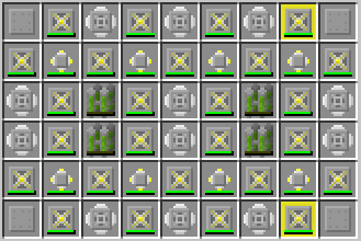
If you want a 4 quad 320EU/t reactor then this design will spread the heat properly. The plating in the corners can be omitted - they're only there to allow the rector to be automated.

sNp04CE.png


The total vent cooling on your design adds up to 332 HU/s, but your heat output in 640 HU/s - so you have 308 excess heat per second, which is being absorbed by your components as damage.

As to the asymmetry of the heat distribution; fuel rods and other components distribute their heat in an order: left, right, down and up. Which can cause issues when the quantity of heat is not evenly divisible by the number of valid sinks as heat is transferred in integer units. And when some adjacent components have already taken all the heat they can in a tick. Some of the more popular asymmetric reactor designs simply cannot work if the layout is mirrored or rotated.

This wiki is helpful: https://ftb.gamepedia.com/Building_safe_nuclear_reactors
 
Last edited:
  • Like
Reactions: ICountFrom0

Brotuulaan

Well-Known Member
Jan 14, 2018
190
38
53
@Pyure, thanks for the link. That should be quite useful. Yes, they usually included very long strings of characters. Can you plug those into this offline planner somehow? That would be useful to put all those conversations into context.

@GreenZombie, thanks for the very specific info! I hadn't even thought about tallying up the heat output and the heat dispersion of my components. This is all very new to me, so my mind isn't tackling all the angles like someone who's done this for a while. And thanks for that design! I'll test that out in the next few minutes! And that's quite interesting, how the heat is moved around. With some asymmetrical designs, do people use reactor heat exchangers to shuffle the heat into other areas of the layout?

And thanks for all the other feedback, everybody!
 
  • Like
Reactions: ICountFrom0

Brotuulaan

Well-Known Member
Jan 14, 2018
190
38
53
And @GreenZombie, do you mean that the plating is for automation so you can input new rods without them going to the wrong place? So those plates are your preferred filler because of the resources that go into them?
 

GreenZombie

New Member
Jul 29, 2019
2,402
-1
0
And @GreenZombie, do you mean that the plating is for automation so you can input new rods without them going to the wrong place? So those plates are your preferred filler because of the resources that go into them?

Exactly that.

@GreenZombie, thanks for the very specific info! I hadn't even thought about tallying up the heat output and the heat dispersion of my components. This is all very new to me, so my mind isn't tackling all the angles like someone who's done this for a while. And thanks for that design! I'll test that out in the next few minutes! And that's quite interesting, how the heat is moved around. With some asymmetrical designs, do people use reactor heat exchangers to shuffle the heat into other areas of the layout?

Quad Fuel Cells generate 96 HU by themselves - 160 HU when adjacent to another rod like in the above design. The best vent only sheds 20 HU from the reactor so you need to use heat exchangers to distribute the heat to enough heat vents.

A different kind of reactor doesn't use any components next to fuel rods that accept "pushed" heat. Reactor Heat Exchangers and Component Heat Vents, plating etc. A Fuel Cell that can't put its heat into a component dumps it into the reactor hull - which is a heat reservoir capable of holding 10,000 heat. Then you would look at components - like the Reactor Heat Exchanger - which can pull heat from the hull without being near the cells - but now you have to cool those. These designs are potentially _very_ asymmetrical as heat is delivered to components by scanning each row from left to right, starting with the top and going down and each component draws its max draw from the hull.

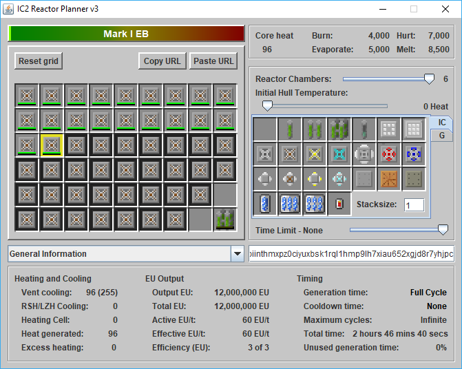
I still prefer using this reactor planner as its interactive so you can easily try different cooling strategies out.
https://forum.feed-the-beast.com/threads/request-for-ic2-reactor-planner-v3-download.164759/

It has the wrong value for how long Fuel Cells last so it miscomputes the Total EU and some of the consumable components have changed mechanics. But, if you stick to the uranium fuel cells, heat vents and heat exchangers, it still models how heat moves in a reactor correctly.

Here it is showing a rather naive way of cooling a reactor via hull cooling, demonstrating which vents actually picked up heat.

FT5w7Cm.png
 
Last edited:

GreenZombie

New Member
Jul 29, 2019
2,402
-1
0
Actually, having tinkered with reactor components in the simulators to understand heat distribution patterns better, I don't think the order that Fuel Cells distribute heat is relevant here. has anything to do with the Fuel Cell heat distribution. While it is defined I haven't had much success getting asymmetrical heat flows out of Fuel Cells. However, you have 4 Reactor Heat Exchangers in the design. And they are positioned above the top and the bottom of the Fuel Cells and effectively isolate the reactor into 3 heat compartments. Left, Centre and Right. Now, Reactor Heat Exchangers are interesting as, when given heat, they tend to dump it into the reactor hull, but they also draw heat FROM the hull. So, as the reactor starts up with a cool hull, they all get given some heat. Some get sucked out by the advanced heat exchangers, but some gets dumped into the hull. Now there is heat in the reactor, and heat is distributed to components by IC2 scanning over the reactor from the top left, and IC2 distributes as much heat as it can to each component it encounters in this scan. This means, each time heat is dumped into the reactor, its going to tend to be seen first by components on the left side.
In theory this could self regulate, as the Reactor Heat Exchangers on the right hand side would be cooler, and tend to draw more heat from the reactor and distribute it on the right, but because you are at such a cooling deficit, they're never cool enough to do anything but push heat.

--
A small refinement to my understanding: When a component dumps heat into the hull, it doesn't actually. First it tries to distribute heat by scanning FROM the component to the right (and down etc.) until it gets back to the component (i.e. doesn't stop when it reaches the bottom) looking for a component that can - and wants to - accept heat. If it can't find a target THEN the heat gets added to the hull heat.

As all the heat exchangers try to exchange heat on the basis of the relative 'temperature' of their connected things they may, or may not, accept heat if their surrounding components are hotter than the hull.

The temperature of any component (including hull) of a reactor is the ratio of the current heat to the max heat.
 
Last edited:

Brotuulaan

Well-Known Member
Jan 14, 2018
190
38
53
Makes sense, given your previous comments. Thanks for helping me understand the process! And I've been running the design you gave earlier, and it's been working great for my needs!
 
  • Like
Reactions: ICountFrom0